|  | |

| ||
| Construction of the prototype mostly followed the design sketch. The luggage compartment opens when needed to a station wagon or pickup truck configuration but is aerodynamically correct when closed. The vehicle weight was only a little over 400 pounds. The Honeywell motors had to be more powerful than those specified on the sketch, and the Dodge coupling and flex shaft wasn't used. 300 MPG at 55 MPH is a realistic goal, but we didn't get very close to that with the prototype. The Gale lawnmower engine and Motorola alternator worked very well, although it was a bit noisy. | ||
| The welded tube body worked well for the prototype. Aircraft design and construction were part of my experience. Everything is out in the open and easy to fit or change. It's all standard aircraft techniques, almost no tooling cost, just a layout on the floor. If you wanted to build more than one exactly the same other methods could probably be better. | 
| |
| The bumper is thin wall conduit with about 3 inches of spring, better protection at low speed than a stndard bumper. Detail design is all standard automotive practice scaled down for our low weight. The bumper, headlights, parking lights, and turn signals are all within legal requirements. We had no trouble getting license plates. | 
| |
| There are no metal springs of any kind. Standard air shocks are the total suspension method. Ground clearence and load equalizing are adjustable. The ride was about the same as any medium size Detroit car, not at all like a go cart. Caster, camber, and toe are all adjustable with ball bearing rod ends. An aluminum hub held bearings, brakes, and suspension mounting points | 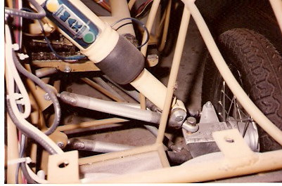
| |
| The rear wheels have a trailing fork suspension with the pivot point the shaft under the motor. It mounts to the frame just behind the seats. The motor is a 3 HP permanent magnet 24 volt made by Honeywell. The right angle drive is a 2 to 1 reduction. The air shock mounts to the reduction drive. The motor was placed so that it exactly balances the weight of the wheel assembly. It's hard to do, but there is NO unsprung weight at the back wheels. | 
| |
| The lawn mower engine mounts to an aluminum deck plate with the drive shaft going down to the Motorola alternator also mounted to the deck. The engine is rated at 3.5 HP and at 90 amps is producing about 2 electrical horse power which is about what it realy takes to keep the vehicle going at constant speed over leval ground. The front suspension air shock mounts to the center beam structure | 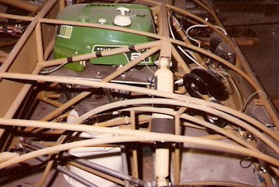
| |
| The electrical controls are standard industrial DPDT lever switches. Under the dashboard is the forward or reverse switch, changing the polarity of the battery output. The next one changes the battery output from parralel to series, from 12 to 24 volts. the next changes the routing to the motors from series to parralel, from the voltage going to each motor or through one motor and then the other. | 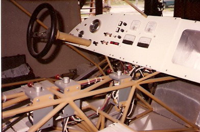
| |
| This is the electrical equivelent of different gears. You start with the batteries parralel and the motors in series. Switch the motors to paralel and each motor gets 12 volts. Switch the batteries to series and each motor gets 24 volts for highway speeds.The reverse is used slowing down for a stop sign or a hill. The regular brakes are used mostly to hold still at a stop sign. The frame is covered with dacron cloth and given several coats of finish that can be just as fancy as you wish, just like a small aircrft wing. This will last many years out in the weather and still be ready to go 150 miles an hour through rain and hail. It's also very easy to repair with minimal tools and experience. We talked about molded composite bodies and automatic controls and quiet gas turbine generators and a lot of other stuff, but I had to leave the area and none of that ever happened. The prototype was lost in a flood not long after I left. | ||
| E MAIL bobfoote@lycos.com | ||