ROCKY RIDGE RESEARCH | ||
|---|---|---|
|  | |
| Fluid in the boiler, 1, is heated by a heat source, 2. The pressurized vapor is conducted to the engine, 3, and the pump, 5, by tubing 14, and controlled by throttle valve, 18. The exhaust from the engine and pump is conducted to the high side of the condenser, 4, by tubing, 15. The low side of the condenser is connected to the suction port of the pump, 5, by tubing, 16. The pressure output of the pump is conducted to the input of the boiler by tubing, 17, through a check valve, 13. | 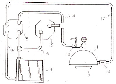
| |
| The expansion device is a 2 cylinder piston engine, 3, created by converting an air conditioning compressor to an engine. The compressor has the valve plate and head removed and replaced by a plate, 6, into which a rotary valve shaft, 7, with a bearing, 8, a shaft seal, 9, and a sprocket, 10, are installed. Another sprocket, 12, with the same pitch as sprocket 10 is installed on the drive shaft of the compressor. | 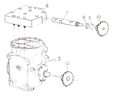
| |
| Detail of rotary valve mechanism. The top view shows the arrangement of the ports and passages in the plate, 6. Section A-A shows a piston at top dead center with the pressure port about to open for 90 degrees of crankshaft rotation. Section B-B shows the same piston at top dead center with the exhaust port just closing after being open for 180 degrees of crankshaft rotation. | 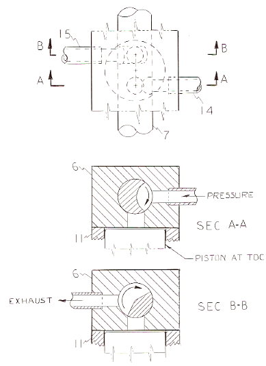
| |
| The heat source, 2, a radiant heating element in the preferred embodiment, 30, is connected to a propane source with a fuel line, 20, and passes through a valve, 19, that is controlled by a thermostat to maintain a desired temperature in the working fluid. The working fluid is heated in the in the boiler, 1, and exits through a throttle valve, 18, that is controlled by well known means to provide a desired output from the engine. The prefered heat source, 30, is a radiant catalytic heating element fueled with propane, but other gases may be used. The heat source may be flue gas from an existing source, wood stove, furnace, fireplace, etc., or a fire box for solid, liquid, or gas fuel provided for that purpose. The flue, 21, is fitted with a diversion damper, 22, to direct gases through the plenum chamber below the boiler. The heat source may also be any medium capable of maintaining working temperatures in the working fluid, such as geothermal, solar, exhaust gases from internal combustion engines, or waste heat from industrial processes. | 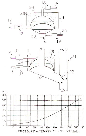
| |
| Assembly drawing of the present invention. The engine, 3 and the pump, 5, are mounted so that roller chain, 27, aligns with sprocket, 26, and drives counter shaft, 25. The primary load, 28, a 4 KW electrical generator in the preferred embodiment, is connected to the engine with suitable means. The secondary load, 29, a battery charging generator, cooling fan, or other accessory is driven by the countershaft. Different heat sources and boilers may be used to deliver pressure to tubing 14. Different engine and pump configurations may be used to expand the working fluid, condense and cool it, and return it to the boiler. The engine and pump configuration described in figure 5 may be altered to become two engines as described to obtain greater power with a standard air conditioning compressor driven by countershaft 25 used to return the fluid to the boiler. | 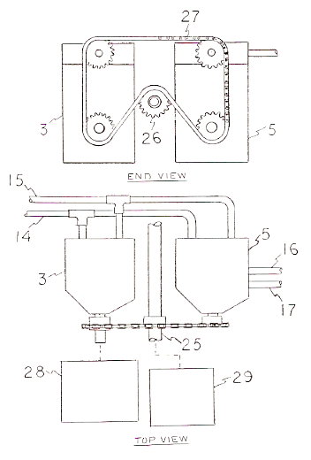
| |
| Conventional automotive air conditioning tools, procedures, and techniques are used to assemble and operate the system. The completed system is evacuated of air and moisture with a vacuum pump and then charged with Freon R-134a. The heat source heats the working fluid in the boiler to less than 200 degrees, a sub-critical temperature that assures working conditions similar to those found in all automotive air conditioning systems. The working fluid is expanded in the engine to provide mechanical power, then cooled in the condenser and returned to the boiler by the pump.
FOR PROTOTYPE--- | ||
| E MAIL bobfoote@lycos.com | ||